CNC Machining Drawing Requirements: What Engineers and Buyers Should Include
What information belongs on a CNC manufacturing drawing?
A CNC drawing should define the part’s geometry, dimensions, units, datums where needed, tolerances, material and condition, threads, surface requirements and revision. A 3D model helps communicate shape, but the parties should agree which document controls manufacturing and inspection requirements.
- Identify critical-to-function features and their acceptance criteria.
- State referenced specifications and clarify requirements that cannot be inferred from the model.
- Define the condition in which dimensions are accepted, including the effect of any finishing operation.
- Resolve conflicting dimensions or revisions before production.
Use the RFQ checklist for quantities, delivery and commercial information that accompanies the drawing. For demanding features, review tolerance and inspection planning.
A good CNC machining project starts before the first tool touches the material.
It starts with a clear manufacturing drawing.
For engineers and procurement teams sourcing custom CNC machined parts, incomplete or ambiguous drawings can create unnecessary questions, quotation differences, manufacturing assumptions, inspection disagreements, and delays.
A well-prepared drawing helps the manufacturer understand exactly what must be produced and how the finished component will be evaluated.
This guide explains what engineers and buyers should include when preparing drawings for CNC machining.
What Should a CNC Machining Drawing Include?
Direct answer: A CNC machining drawing should clearly define the part geometry, dimensions, tolerances, material, threads, GD&T where required, surface-finish requirements, secondary processes, critical characteristics, drawing revision, and applicable inspection or documentation requirements.
For most precision-machining projects, the manufacturer may also need a 3D CAD model.
The 3D model communicates geometry efficiently, while the controlled 2D drawing defines manufacturing and acceptance requirements that may not be completely represented in the model.
Do CNC Manufacturers Need Both 2D Drawings and 3D CAD Files?
Direct answer: For many precision CNC machining projects, providing both a 3D CAD model and a controlled 2D engineering drawing is useful. The 3D model defines component geometry, while the 2D drawing can communicate tolerances, GD&T, threads, surface finish, material, inspection requirements, and other manufacturing notes.
They perform different roles.
3D CAD Model
The CAD model helps communicate:
- complete part geometry
- surfaces and contours
- pockets
- holes
- complex features
- machining access.
2D Engineering Drawing
The drawing can define:
- critical dimensions
- tolerances
- GD&T
- datum structure
- threads
- surface roughness
- material
- heat treatment
- surface treatment
- inspection requirements
- revision information.
For precision manufacturing, relying on only one source can leave important requirements unclear.
1. Drawing Revision
Every controlled manufacturing drawing should clearly identify its revision.
This becomes particularly important for repeat production.
If engineering changes a feature but the manufacturer works from an older revision, the resulting parts may be dimensionally correct to the wrong specification.
Buyers should therefore ensure that the:
Drawing + CAD model + Purchase Order + RFQ
all reference the appropriate revision.
For repeat-production programs, revision control becomes part of the broader quality system.
Learn more about TDB Hanoi’s CNC Machining Quality Assurance.
2. Material and Material Grade
Avoid specifying only:
Aluminum
or:
Stainless Steel
when the actual material grade is important.
The drawing or RFQ should identify the required material as specifically as the project requires.
Material selection can affect:
- strength
- corrosion resistance
- weight
- machinability
- dimensional stability
- surface treatment
- manufacturing cost.
TDB Hanoi’s CNC Machining Materials guide explains the relationship between material selection and machining.
For aluminum applications, also see our Aluminum 6061 vs 7075 for CNC Machining comparison.
3. Dimensions
The drawing should contain the dimensions necessary to manufacture and inspect the component.
However, more dimensions do not automatically make a better drawing.
Dimensions should communicate design intent clearly without creating unnecessary conflicts or ambiguity.
Critical dimensions should be identifiable and consistent with the part’s functional requirements.
4. Dimensional Tolerances
A nominal dimension alone does not tell the manufacturer how much variation is acceptable.
Tolerance defines the permitted dimensional variation.
Tolerances may be specified individually or through an applicable general tolerance system where appropriate.
The key principle is:
Specify tolerances according to functional requirements.
Unnecessarily restrictive tolerances can increase:
- machining time
- setup requirements
- inspection
- tooling requirements
- scrap risk
- manufacturing cost.
Our Tight Tolerance CNC Machining Guide explains these considerations in more detail.
5. GD&T and Datum References
Some functional relationships cannot be communicated adequately with simple ± dimensional tolerances.
Geometric Dimensioning and Tolerancing can define requirements involving:
- flatness
- straightness
- parallelism
- perpendicularity
- position
- circularity
- cylindricity
- profile
- runout.
Datum references establish the coordinate framework from which related features can be evaluated.
If the component uses geometric tolerancing, the drawing should communicate the GD&T requirements and datum structure clearly.
Read our complete GD&T for CNC Machined Parts guide.
6. Hole Requirements
Hole information should be clearly defined.
Depending on the design, this may include:
- diameter
- depth
- through or blind condition
- tolerance
- countersink
- counterbore
- spotface
- positional requirement
- thread requirement.
A 3D model may show the geometry of a hole but may not communicate every manufacturing and inspection requirement.
7. Thread Specifications
Threads require more information than simply showing a cylindrical feature in CAD.
The drawing should identify the appropriate thread specification.
Depending on the project, relevant information may include:
- thread type
- nominal size
- pitch
- class or fit where required
- thread depth
- through or blind condition.
Thread requirements should be explicit rather than left for the manufacturer to infer from the model.
8. Surface Finish Requirements
Surface requirements can influence both function and manufacturing cost.
Depending on the component, the drawing may need to define:
- required surface roughness
- critical functional surfaces
- cosmetic surfaces
- as-machined condition
- secondary finishing
- areas that must not receive a coating
- special surface requirements.
Do not apply restrictive surface requirements to every surface unless the function actually requires them.
Our CNC Machining Surface Finishes guide explains how machining and finishing requirements interact.
9. Secondary Processes
If the component requires operations after machining, identify them during quotation.
Examples may include project-specific:
- anodizing
- passivation
- plating
- coating
- painting
- heat treatment
- grinding
- marking.
Secondary operations can affect dimensions, surfaces, masking requirements, lead time, inspection, and cost.
The supplier should therefore know about them before manufacturing planning begins.
10. Critical Characteristics
Not every feature on a component has equal functional importance.
Where appropriate, drawings and supporting quality documents should identify critical characteristics.
Examples might include:
- mating surfaces
- bearing fits
- sealing surfaces
- hole patterns
- alignment features
- critical diameters
- assembly interfaces.
Knowing which features are functionally important helps manufacturing and quality teams develop appropriate process and inspection plans.
11. Inspection Requirements
Do not wait until the parts are complete to determine what inspection documentation is required.
Buyers should communicate requirements such as:
- dimensional inspection
- critical-feature inspection
- first-article requirements
- CMM inspection where applicable
- inspection records
- material documentation
- project-specific reports.
The required scope should be agreed before production.
TDB Hanoi’s Quality Control page explains our approach to project-specific inspection requirements.
12. Surface Treatment and Dimensional Allowance
Secondary finishing can affect component dimensions.
This is especially important for:
- fits
- threads
- holes
- mating surfaces
- sealing areas
- precision interfaces.
Where relevant, the drawing should identify surfaces requiring treatment and areas requiring masking or dimensional consideration.
Surface treatment should be part of manufacturing planning rather than an afterthought.
13. Units
The drawing should clearly establish the measurement system being used.
Do not force the manufacturer to guess whether dimensions are expressed in:
millimeters or inches.
This sounds simple, but clarity at drawing level helps eliminate avoidable manufacturing assumptions.
14. General Notes
Engineering drawings often contain general notes applying to the entire component.
These may cover requirements such as:
- deburring
- edge conditions
- cleaning
- workmanship
- general tolerances
- material
- finishing
- inspection.
General notes should be clear, relevant, and consistent with the rest of the drawing.
CNC Milling Drawing Requirements
For CNC-milled components, drawing clarity becomes particularly important when the part contains:
- multiple machined faces
- deep pockets
- thin walls
- hole patterns
- complex datums
- critical mounting surfaces.
The manufacturing team may need to plan several setups while maintaining relationships between features.
See TDB Hanoi’s CNC Milling Services for more information.
CNC Turning Drawing Requirements
For turned components, drawings may need to communicate:
- diameters
- lengths
- shoulders
- grooves
- threads
- bores
- concentric relationships
- runout
- surface requirements.
A rotational component can also require secondary milling.
Our CNC Milling vs Turning guide explains how part geometry influences process selection.
See TDB Hanoi’s CNC Turning Services for additional capability information.
Should You Specify the CNC Manufacturing Process?
Direct answer: Not always. If a particular process is functionally required, it should be specified. Otherwise, clearly defining the component’s geometry, material, tolerances, GD&T, surface requirements, quantity, and acceptance criteria can allow the manufacturer to review an appropriate production method.
For example, a component containing both rotational and prismatic features may require a combination of processes.
Over-specifying the manufacturing method can sometimes limit DFM opportunities.
How Drawing Requirements Affect CNC Machining Cost
A drawing is also a major cost driver.
Cost can increase because of:
- unnecessarily tight tolerances
- difficult-to-machine geometry
- excessive setup requirements
- restrictive surface finishes
- special materials
- complex inspection requirements
- secondary operations.
This does not mean requirements should be relaxed simply to reduce price.
It means each requirement should exist for an engineering reason.
Read our How to Reduce CNC Machining Cost guide for additional DFM considerations.
What Information Should Accompany the Drawing?
A complete RFQ should normally provide more than the engineering drawing itself.
Depending on the project, send:
- 2D drawing
- 3D CAD file
- drawing revision
- material and grade
- order quantity
- annual forecast where relevant
- critical tolerances
- surface-finish requirements
- secondary processes
- inspection requirements
- documentation requirements
- packaging requirements
- delivery requirements.
For a complete purchasing workflow, see our CNC Machining RFQ Vietnam Guide.
What File Formats Should You Send?
For precision machining projects, the most important requirement is that the manufacturer receives controlled technical information that accurately communicates the design.
Common 3D exchange formats may include STEP or other agreed CAD formats.
The 2D drawing is commonly provided as a controlled PDF or another agreed engineering-document format.
If multiple files are supplied, make sure they correspond to the same revision.
Can you order CNC parts with only a sample or incomplete CAD?
You can begin a sourcing discussion with a physical sample or incomplete CAD, but these inputs do not automatically define a production-ready component. A supplier may be able to discuss feasibility or provide a conditional budget estimate. Before production, agree who will create, verify and approve the missing manufacturing requirements.
Separate what the sample shows from what the design requires
A measurement describes the sample in its present condition. It does not automatically establish the original nominal size or tolerance. Wear, damage, coatings or earlier manufacturing variation can affect the observed geometry. Tell the reviewer whether the sample is new, used, repaired or known to be nonconforming.
A geometric scan or model reconstruction does not by itself establish material grade, heat treatment, original acceptance limits or suitability for the intended application. Keep those unknowns visible and define the evidence or engineering decision needed to resolve them.
| Available input | Useful for | Still needs agreement |
|---|---|---|
| Photographs | Explaining appearance, context and obvious interfaces. | Dimensions, material, tolerances and a controlled definition. |
| Physical sample | Observation and measurement of that object. | Nominal values, original intent, wear assessment and acceptance limits. |
| 3D CAD without notes | Communicating geometry and discussing a possible process. | Material, finish, tolerances, critical features and file precedence. |
| Old or conflicting files | Understanding the design history. | Which approved revision governs the new order. |
Approve the definition before releasing production
Create an open-question register covering geometry, datums, fits, material condition, treatment, finish and inspection. Identify the responsible designer or other approval authority for each decision. Record the approved drawing/model revision and the rule for resolving conflicts between files.
If measurement, modeling, drawing creation or testing is needed, ask whether it can be supported and how it will be scoped and priced. Do not assume these activities are included in machining or that TDB offers every reconstruction method. Any such work needs explicit project confirmation.
Share only samples and data you are authorized to use for the project. Agree handling, identification and return of physical samples, especially if a sample is unique or may be affected by a proposed test. The buyer should resolve permission and design ownership before authorizing reproduction.
Use staged technical and commercial approval
- Describe the application, available inputs and known unknowns.
- Agree any data-capture or engineering deliverables and their limits.
- Review and approve the controlled manufacturing definition.
- Confirm the quotation scope, inspection requirements and exclusions.
- Approve trial evidence and the conditions for any production release.
A budget estimate made before those decisions should identify its assumptions. It is not the same as a production quotation against a settled specification. Use the RFQ preparation guide for the full package and the revision-control guide to manage approval changes.
What should you send if you only have a sample?
Provide photographs, the intended application, relevant mating information, known specifications, sample condition, required quantity and delivery objective. Identify requirements you do not know rather than filling them with assumptions. For fixture or automation components, include the functional interface information.
Frequently asked questions
Can a sample define the original tolerances?
Not by itself. Measured dimensions describe the sample, while the intended tolerance range must come from an approved design or an agreed engineering definition.
Does a 3D scan identify the original material and treatment?
Geometric capture does not, by itself, establish material grade or treatment. Those requirements need their own evidence or verification.
Can production start while the drawing is still being recreated?
Use a defined approval gate. Resolve the manufacturing definition and acceptance requirements before authorizing production under the agreed scope.
Tell TDB Hanoi what files and samples are available and which requirements remain unresolved. Request a scope review before assuming measurement, reconstruction, testing or production can be included.
Drawing Review Before CNC Production
Direct answer: A CNC manufacturer should review the drawing before production to identify unclear requirements, critical features, material specifications, tolerances, GD&T, surface requirements, inspection needs, and potential manufacturability issues.
The ideal workflow is:
Drawing → Engineering Review → Technical Clarification → Quotation → Approved Requirements → Production → Inspection
Not:
Quotation → Production → Discover Requirements Later
Early review can reduce assumptions and technical misunderstandings.
Drawing Requirements for International CNC Sourcing
Clear drawings become even more important when working with an international supplier.
Engineering intent needs to travel across:
- organizations
- engineering teams
- procurement teams
- languages
- manufacturing departments
- quality departments.
The drawing therefore becomes one of the most important controlled communication tools in the project.
US companies developing a Vietnam manufacturing source can read our How to Source CNC Parts from Vietnam guide.
Companies comparing sourcing locations can also review CNC Machining Vietnam vs USA.
CNC Drawing Review at TDB Hanoi
TDB Hanoi manufactures custom components according to customer drawings and agreed project requirements.
Before production, project requirements can be reviewed together with:
- component geometry
- material
- tolerances
- GD&T
- critical features
- surface requirements
- manufacturing process
- inspection requirements
- production quantity
- documentation requirements.
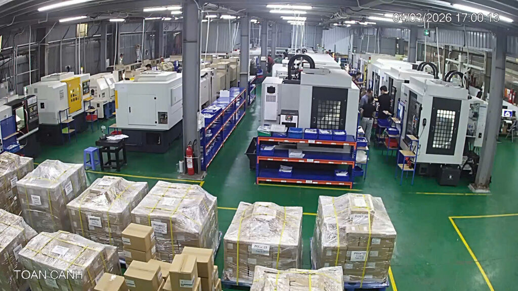
TDB Hanoi operates 50+ CNC machines and supports production capacity of up to 200,000 parts per month across its manufacturing operations.
Our capabilities include CNC Machining Services, CNC milling, CNC turning, Swiss machining, contract manufacturing, and broader manufacturing support for custom components.
Frequently Asked Questions
What should be included in a CNC machining drawing?
A CNC machining drawing should clearly communicate geometry, dimensions, tolerances, material, threads, GD&T where applicable, surface requirements, secondary processes, revision, and relevant inspection requirements.
Do I need a 2D drawing if I already have a 3D CAD model?
For many precision-machining projects, a controlled 2D drawing remains useful because it can communicate tolerances, GD&T, threads, finishes, inspection requirements, and other information not fully defined by geometry alone.
Should tolerances be included on the CNC drawing?
Yes. Critical dimensional requirements should be communicated clearly. General tolerances may also be specified where appropriate.
Should GD&T be included?
GD&T should be used where it appropriately communicates functional geometric requirements. It is not necessary to apply GD&T to every component or every feature.
Should material grade be shown on the drawing?
Where the specific material grade is important, it should be clearly defined in the controlled project documentation.
Should surface finishing be specified before quotation?
Yes. Surface treatment and finishing can affect manufacturing process, dimensions, cost, inspection, and lead time.
What should I send with my CNC drawing for quotation?
Provide the drawing together with CAD data where available, quantity, material, tolerances, finishing, inspection, documentation, packaging, and delivery requirements.
Can TDB Hanoi review a drawing before quotation?
Yes. Customers can send drawings and project requirements to TDB Hanoi for manufacturing review before quotation.
Send Your CNC Drawing to TDB Hanoi
A clear engineering drawing helps create a clear manufacturing process.
If you are sourcing custom CNC machined parts, send TDB Hanoi your:
2D Drawing · 3D CAD · Material · Quantity · Tolerances · GD&T · Surface Requirements · Inspection Requirements
Our team can review the manufacturing requirements before quotation.