GD&T for CNC Machined Parts: A Practical Guide for Engineers and Buyers
Geometric Dimensioning and Tolerancing (GD&T) is a system used on engineering drawings to define the allowable variation of part geometry and the relationships between features.
For CNC machined parts, GD&T helps designers, manufacturers, and inspectors communicate more clearly about how a component must function—not simply how large or small an individual dimension can be.
When sourcing precision CNC parts, correctly defined GD&T can reduce ambiguity during quotation, manufacturing, and inspection.
What Is GD&T in CNC Machining?
Direct answer: GD&T, or Geometric Dimensioning and Tolerancing, is a standardized engineering language used to control the form, orientation, location, and runout of part features. In CNC machining, it helps communicate how critical features must relate to one another so the finished component can meet its intended fit and function.
Traditional dimensional tolerances may define the acceptable size of a feature.
GD&T can additionally define relationships such as:
- how flat a surface must be
- how perpendicular one feature must be to another
- where a hole must be positioned
- how parallel two surfaces must remain
- how a rotating feature must behave relative to a datum.
This makes GD&T particularly useful for precision components where functional relationships between features are important.
Why Is GD&T Important for CNC Machined Parts?
A component can meet individual dimensional tolerances and still fail to function correctly if important geometric relationships are not controlled.
Consider a mounting plate containing several holes.
Knowing each hole diameter alone may not be sufficient.
The assembly may also depend on:
- the location of the holes
- their relationship to reference surfaces
- surface flatness
- perpendicularity
- the relationship between multiple features.
GD&T gives the designer a structured way to communicate those requirements.
For the CNC manufacturer, it provides important information for process planning and inspection.
Dimensional Tolerance vs GD&T
Dimensional tolerances and GD&T perform related but different roles.
A dimensional tolerance may specify an acceptable range for a size or distance.
For example:
Diameter: 10.00 ± 0.05 mm
This controls the permitted size variation.
GD&T can control geometric characteristics and relationships that a simple ± tolerance may not fully describe.
Examples include:
- flatness
- straightness
- circularity
- cylindricity
- parallelism
- perpendicularity
- angularity
- position
- profile
- runout.
The correct method depends on the function of the component and the design requirements.
What Are Datums in GD&T?
A datum establishes a reference from which another feature or geometric requirement can be evaluated.
For CNC machining, datum selection can influence both manufacturing and inspection strategy.
A drawing may establish primary, secondary, and tertiary datum references to create a reference framework for the component.
For example:
Datum A → primary mounting surface
Datum B → secondary locating surface
Datum C → tertiary locating feature
Other features can then be controlled relative to this reference system.
Clear datum definition can help manufacturing and inspection teams understand how the component is intended to locate and function in the final assembly.
Common GD&T Controls for CNC Machined Parts
Flatness
Flatness controls how much a surface may vary from an ideal flat plane.
It does not require a datum reference.
Flatness may be important for:
- mounting surfaces
- sealing surfaces
- mating faces
- precision interfaces.
Straightness
Straightness controls the permitted variation of a line element or, in applicable cases, an axis or derived median line.
For machined components, it may be relevant to long features, shafts, guide surfaces, or other geometry where straightness affects function.
Parallelism
Parallelism controls the orientation of a feature relative to a datum.
It can be important where two surfaces or axes must maintain a controlled relationship.
Perpendicularity
Perpendicularity controls orientation relative to a datum at 90 degrees.
Typical CNC applications can include:
- shoulders
- mounting faces
- holes
- bores
- mating features.
Position
Position is widely used to control the location of features such as holes, bores, pins, and patterns relative to defined datums.
For assemblies containing multiple fasteners or locating features, position can communicate functional requirements more effectively than independent coordinate tolerances.
Circularity
Circularity controls the form of individual circular elements.
It can be relevant for turned components and other circular features where form affects fit or function.
Cylindricity
Cylindricity controls the overall form of a cylindrical surface.
It may be relevant for shafts, bores, sleeves, and other precision cylindrical components.
Profile
Profile controls can define the allowable variation of a line or surface relative to its theoretically exact geometry.
They can be useful for complex contours and surfaces where conventional coordinate dimensioning becomes difficult.
Runout
Runout controls variation of a surface during rotation relative to a datum axis.
It is particularly relevant to rotational components such as:
- shafts
- bearing surfaces
- rotating sleeves
- precision turned components.
GD&T and CNC Milling
GD&T is frequently used on CNC-milled components containing multiple related surfaces, holes, pockets, and locating features.
For example, a machined housing may require:
- flatness on a mounting surface
- perpendicularity between faces
- position for a bolt-hole pattern
- parallelism between mating surfaces.
These requirements can influence setup strategy, workholding, machining sequence, and inspection.
For more information about this manufacturing process, see TDB Hanoi’s CNC Milling Services.
GD&T and CNC Turning
Turned components can also contain important geometric controls.
A shaft, for example, may require control of:
- circularity
- cylindricity
- perpendicular shoulders
- concentric relationships
- runout
- feature position.
Parts combining rotational and non-rotational features may require both turning and secondary milling.
Our CNC Milling vs Turning guide explains how component geometry influences process selection.
Learn more about TDB Hanoi’s CNC Turning Services.
How Does GD&T Affect CNC Machining Cost?
GD&T itself does not automatically make a part expensive.
However, restrictive geometric requirements can increase manufacturing cost when they require additional:
- setups
- fixtures
- process control
- machining operations
- finishing passes
- inspection
- measurement time.
This is why tolerances should reflect functional requirements.
Applying very restrictive controls to noncritical features can add manufacturing and inspection effort without improving the performance of the final assembly.
For related DFM considerations, read our How to Reduce CNC Machining Cost guide.
GD&T and Tight Tolerance Machining
GD&T and tight dimensional tolerances are closely related, but they are not the same thing.
A tight dimensional tolerance controls allowable dimensional variation.
A geometric tolerance controls characteristics such as form, orientation, location, or runout.
Precision components may require both.
The important point is to identify which characteristics are actually critical to function.
Read our Tight Tolerance CNC Machining Guide for a deeper discussion of tolerance planning.
How Is GD&T Inspected?
Direct answer: The appropriate GD&T inspection method depends on the characteristic being controlled, the tolerance, component geometry, datum structure, quantity, and agreed inspection requirements. Measurement equipment should be selected according to the drawing and the feature being verified.
Depending on the requirement, inspection may involve different dimensional measurement methods.
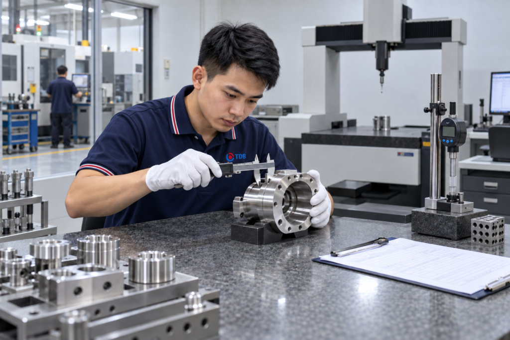
Complex geometric relationships may require coordinate measurement or other appropriate inspection equipment.
TDB Hanoi’s manufacturing quality approach includes incoming, in-process, and final controls, with inspection requirements reviewed according to the drawing and project requirements.
See our CNC Machining Quality Assurance page for more information.
Can a CMM Inspect GD&T?
Direct answer: A coordinate measuring machine (CMM) can be used to evaluate many GD&T characteristics by measuring component features relative to defined datums. Whether CMM inspection is appropriate depends on the specific characteristic, tolerance, part geometry, measurement strategy, and project requirements.
Owning a CMM alone does not guarantee that every GD&T requirement can automatically be inspected correctly.
The measurement strategy must correspond to the engineering drawing and acceptance requirements.
This distinction is important when qualifying a CNC machining supplier.
GD&T Standards: ASME Y14.5 and ISO 1101
Two important references used in geometrical tolerancing are ASME Y14.5 and ISO 1101.
ASME Y14.5 establishes rules, symbols, definitions, and practices for dimensioning and tolerancing used on engineering drawings and related product-definition documents.
ISO 1101 defines the symbol language and interpretation rules for geometrical specification of workpieces.
The applicable standard should be identified by the customer or engineering documentation when required.
Manufacturers should not assume which drawing standard applies when the requirement is unclear.
What Should Buyers Send to a CNC Manufacturer?
For parts containing GD&T requirements, buyers should provide a complete manufacturing package whenever possible.
This may include:
- current 2D engineering drawing
- drawing revision
- 3D CAD model where available
- material and grade
- quantity
- dimensional tolerances
- GD&T callouts
- datum references
- surface-finish requirements
- secondary processes
- inspection requirements
- required quality documentation.
This allows the manufacturer to review both machining and inspection requirements before production.
For a complete sourcing checklist, see our CNC Machining RFQ Vietnam Guide.
Review GD&T Before Quotation
A strong CNC sourcing process should not wait until final inspection to discuss GD&T.
Important geometric requirements should be reviewed during quotation.
The manufacturer should understand:
Drawing → Datums → Critical Features → Manufacturing Process → Inspection Method → Acceptance Requirements
before production begins.
This is particularly important for international sourcing, where unclear requirements can create unnecessary communication, rework, or inspection disagreements.
Our How to Source CNC Parts from Vietnam guide explains how drawing and quality requirements fit into supplier qualification.
GD&T for Repeat Production
Repeat manufacturing requires more than producing one acceptable sample.
Critical geometric relationships should remain controlled across production batches.
For repeat orders, buyers should consider:
- drawing revision control
- critical-to-quality characteristics
- manufacturing setup
- inspection frequency
- measurement method
- documentation requirements
- corrective-action process.
This connects GD&T directly to quality planning rather than treating it simply as drawing notation.
GD&T and Material Selection
Material behavior can influence the ability to manufacture and maintain geometric requirements.
Relevant factors can include:
- material stability
- component geometry
- wall thickness
- machining sequence
- residual stress
- thermal effects
- workholding.
Material, geometry, and tolerances should therefore be reviewed together.
See TDB Hanoi’s CNC Machining Materials guide for broader material-selection considerations.
For aluminum components, also see our Aluminum 6061 vs 7075 for CNC Machining comparison.
GD&T and Surface Finish Are Different Requirements
Geometric tolerance and surface finish should not be confused.
GD&T controls geometry and relationships between features.
Surface-finish requirements describe characteristics of the component surface.
A critical feature may require both geometric control and a defined surface requirement.
Our CNC Machining Surface Finishes guide explains surface requirements in more detail.
How Should Buyers Evaluate a CNC Supplier for GD&T Parts?
Do not evaluate the supplier only by asking:
“What tolerance can your machines hold?”
Instead ask:
- Can you interpret the complete drawing?
- How will the datums be established?
- Which features are critical?
- What machining strategy will be used?
- How will the required characteristics be inspected?
- What inspection documentation is required?
- Can the process be repeated consistently?
The real objective is not achieving the smallest possible tolerance.
It is producing components that consistently satisfy the specified engineering requirements.
GD&T Review at TDB Hanoi
TDB Hanoi manufactures custom CNC components according to customer drawings and agreed project requirements.
Our engineering and quality review can consider:
- drawing revision
- material
- dimensions and tolerances
- GD&T requirements
- critical features
- machining process
- surface requirements
- inspection requirements
- production quantity
- required documentation.
TDB Hanoi provides CNC Machining Services in Vietnam including CNC milling, CNC turning, and other manufacturing support for custom components.
Project-specific requirements should be communicated during RFQ so they can be reviewed before quotation and production.
Frequently Asked Questions About GD&T for CNC Machining
What does GD&T mean in CNC machining?
GD&T stands for Geometric Dimensioning and Tolerancing. It provides a standardized way to define allowable geometric variation and relationships between component features.
Why is GD&T important for CNC parts?
GD&T can communicate functional geometric relationships more clearly than simple dimensional tolerances alone, helping manufacturing and inspection teams understand critical design requirements.
Is GD&T the same as dimensional tolerance?
No. Dimensional tolerance generally controls allowable variation in size or distance, while GD&T can control form, orientation, location, profile, and runout.
Does every CNC machined part need GD&T?
No. The appropriate drawing method depends on component design and functional requirements. GD&T is particularly useful when geometric relationships between features are important.
Can CNC milling and turning parts use GD&T?
Yes. GD&T can be applied to both milled and turned components.
Can a CMM measure GD&T?
A CMM can evaluate many GD&T characteristics when an appropriate measurement strategy is used. The correct inspection method depends on the specific drawing requirement.
Should GD&T requirements be provided before quotation?
Yes. Important geometric and inspection requirements should be included during RFQ so the manufacturer can evaluate machining and inspection requirements before quotation.
Which GD&T standard should be used?
The applicable drawing or project standard should be specified by the customer when required. ASME Y14.5 and ISO 1101 are important standards used for dimensioning and geometrical tolerancing.
Discuss Your GD&T and CNC Machining Requirements
If your component contains critical dimensional or geometric requirements, send TDB Hanoi the latest engineering drawing together with:
2D Drawing · 3D CAD · Material · Quantity · Tolerances · GD&T · Surface Requirements · Inspection Requirements
Our team can review the manufacturing and inspection requirements before quotation.